I was perusing DeviantArt looking at some of the maps, and map styles, that people have dreamed up. Some people are very creative in their cartographer. Some of them are truly works of art. I'm not sure this one fall into that category, but it sure is creative. It may be useful, too, if you want to know where the US, Canada, England, Russia, Japan, etc. lie in relation to Middle Earth, Westeros, and Tamriel.

This blog covers my adventures in reading, writing, procedural content generation, and whatever else comes to mind.
Showing posts with label planets. Show all posts
Showing posts with label planets. Show all posts
Sunday, November 12, 2017
Friday, February 10, 2017
Miscellaneous thoughts
In addition to working, walking, and eating, today I watched The Lego Batman Movie, an amusing new animated feature. It was a lot of fun and will likely produce a review in the next couple days. I'm continuing the cleanup of the Plate Tectonics code, and have finished updating the parameters export to cover all the new parameters. A few fresh example worlds are shown below. In a way, I've gotten sick of hearing about politics, but like a car wreck I find it hard to look away. I'm putting the Colonize program I described yesterday onto the back burner, but when I return to it I shall ponder renaming the method for natural population growth from the present four letter word to simply Procreate. 😉
Tonight was a big improvement over last night, and was quite neat with the moon. Tomorrow is looking to be quite lovely weather-wise. Hopefully, I shall spend a chunk of the day outside enjoying it.
Tonight was a big improvement over last night, and was quite neat with the moon. Tomorrow is looking to be quite lovely weather-wise. Hopefully, I shall spend a chunk of the day outside enjoying it.
 |
| World created using seed 14 and one tectonic cycle. |
 |
| World created using seed 14 and two tectonic cycles. Parameters otherwise were the same as above. Note the rugged coasts and high mountains, typical of multiple tectonic cycles. |
 |
| World created using seed 7 and one tectonic cycle. Note only a few high mountains, and smoother coasts, typical of one cycle only. |
Colonize
One last example before I go to bed. I didn't realize how late it had gotten until just now. The Colonize program is designed as a crude and by-no-means science-based model for seaborne colonization from... elsewhere. It's had all of four hours work. It is very much a work in progress, though it'll probably go on the back burner for a while. I want to get back to writing The Forbidden Valley, and there's still the last cleanup activities for Plate Tectonics simulation. But it sure is colorful, and shows some potential, so I thought I'd share the image.
 |
| Colonization in progress of a world generated by Plate Tectonics. Colors represent owning country, and white represents uncolonized lands. |
 |
| World generated by Plate Tectonics simulation |
Thursday, February 9, 2017
Plate Tectonics - 13
I decided to take a brief break from wrapping up the Plat Tectonics simulator work to actually play with it and see about using the generated elevation data in other programs.
First off, I modified my C# port of Amit Patel's polygon map generator to support imported elevation data. There's still some incomplete features in this program, especially with my "Tolkien-esque" rendering mode. When using imported elevation data, sometimes the river networks have anomalies, caused by low spots - "dips" or "holes" - within continental interiors. This could be addressed either within the Plate Tectonics simulator or within the map program.
I've also implemented an import mode for the planet generator I've mentioned in posts past. For terrestrial planets, it usually uses 3D Perlin noise to create the elevation map of the world. With the import, it uses the imported elevation data instead of the noise.
 |
| Graphical output from Plate Tectonics simulator. Single-precision floating-point data is actually used for interchange. |
First off, I modified my C# port of Amit Patel's polygon map generator to support imported elevation data. There's still some incomplete features in this program, especially with my "Tolkien-esque" rendering mode. When using imported elevation data, sometimes the river networks have anomalies, caused by low spots - "dips" or "holes" - within continental interiors. This could be addressed either within the Plate Tectonics simulator or within the map program.
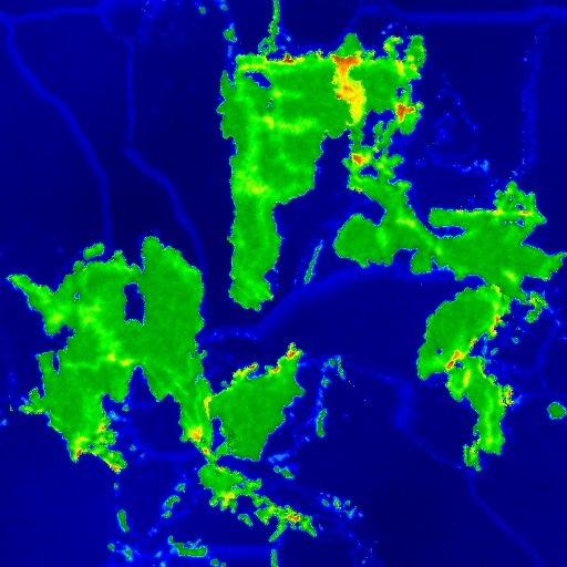
 |
| Elevation data from Plate Tectonics simulator was the data source for this image in a polygonal map generator. |
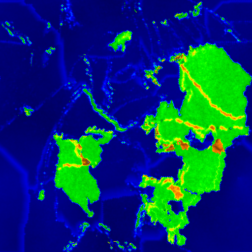
 |
| Close-up of the northwestern continent, in Biome view. |
 |
| Close-up of part of the map, in "Tolkien" view |
 |
| Map created from importing the elevation data into Planets program |
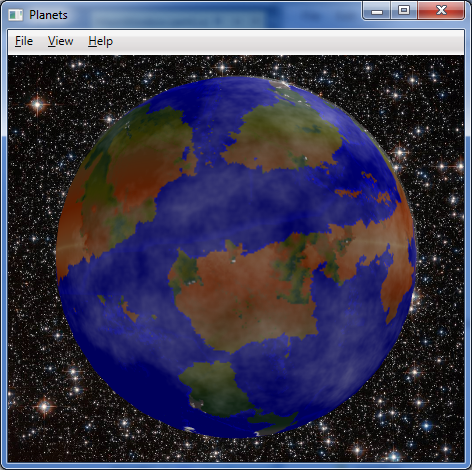 |
| The map wrapped around a globe, with some fractal clouds partially shrouding the planet. |
Wednesday, February 8, 2017
Plate Tectonics - 12
It is all over but the cleanup. The algorithms are all working about as I'd like. I understand the erosion algorithms a lot more now. The original version of PlaTec from several years ago used a modified image smoothing algorithm for erosion. The 2015 version incorporated, in sequence, a hydraulic erosion model (rain drop method), the adding of some random noise to the elevation, and then a super-simplified but effective approximation of thermal erosion. Run it too frequently, and the continent would erode away to sea level, but often in the interior before along the coasts.
Because of some of the abnormalities (the "caterpillars" and eroded mountains) and that tendency, I added a coastal erosion process that lessens the elevation of cells adjacent to water, and run the main erosion algorithm less frequently. I also increased the threshold for the main erosion algorithm, reducing over-erosion of the continental land masses.
About my only complaint is the high degree of variability in the "quality" of the results for a given set of parameters (other than the random number generator seed). The majority of results are acceptable, but some oddities can show up, and you never know if you'll get them or not. So this isn't greatly amenable to fully automated operation; a person should definitely review results for suitability.
So what's left before release? Just the cleanup. I have a variety of debug outputs that need to removed. There are a handful of functions that should ideally be made members of classes if possible - in one case, I'm not sure its possible due to how FLTK callbacks work. I guess I'll find out. I drastically increased the number of simulation parameters that were exposed. However, the export code only currently writes out the few parameters that were originally exposed. So that will need to be updated. I suppose it could also use a quick document describing the simulation parameters and how to accomplish different basic goals with them can be accomplished. Then to GitHub with the lot of it.
 |
| Example 1 |
Because of some of the abnormalities (the "caterpillars" and eroded mountains) and that tendency, I added a coastal erosion process that lessens the elevation of cells adjacent to water, and run the main erosion algorithm less frequently. I also increased the threshold for the main erosion algorithm, reducing over-erosion of the continental land masses.
 |
| Example 2 |
About my only complaint is the high degree of variability in the "quality" of the results for a given set of parameters (other than the random number generator seed). The majority of results are acceptable, but some oddities can show up, and you never know if you'll get them or not. So this isn't greatly amenable to fully automated operation; a person should definitely review results for suitability.
 |
| Example 3 |
So what's left before release? Just the cleanup. I have a variety of debug outputs that need to removed. There are a handful of functions that should ideally be made members of classes if possible - in one case, I'm not sure its possible due to how FLTK callbacks work. I guess I'll find out. I drastically increased the number of simulation parameters that were exposed. However, the export code only currently writes out the few parameters that were originally exposed. So that will need to be updated. I suppose it could also use a quick document describing the simulation parameters and how to accomplish different basic goals with them can be accomplished. Then to GitHub with the lot of it.
 |
| Parameters - these should all be written to file when exporting image or elevation data |
Sunday, February 5, 2017
Plate Tectonics - 11
Well, never mind then. I understand where the problems I'm running into with non-power-of-two dimensions comes from. It comes from the multitude of bit-wise operations that depend upon the width or height of the map being a power of two. One less than a power of two results in a "mask" with all the bits below the bit for that power being set to one. That is, if the value is 8, the binary is 1000, but if the value is 7, the binary is 0111. So a bit-wise AND operation of a coordinate and the length of a side of the map would result in a value that was always within the range of the map side's length - but only if the side (width or height) is a power of two. If the dimension was seven, the binary would be 0111, but binary for one less would be 0110. That screws things up.
The code is riddled with statements like
if (area[i].lft == ((lft + 1) & (map_width-1)))
and
size_t k = (y & (map_height - 1)) * map_width + (x & (map_width - 1));
They are short, terse, and computationally inexpensive, but they fail to work properly when the map_width and map_height values are not powers-of-two. I started to rewrite code to address it, and was making a little progress. Unfortunately the end product is several extra lines of code for each such instance, and involves more computationally expensive (costly) operations than a simple bit-wise AND and a subtraction operation. After 90 minutes of work, it was almost right in one function, as shown below.
But not quite right. And that was in only one function among several, and many of those functions made far heavier use of those AND operations. So I made up my mind. Rather then go through the many hundreds of lines of code that use such statements, and rewrite them into more computationally expensive (costly) operations and adding many news lines of and taking perhaps another dozen hours, I shall give up on non-power-of-two dimensions for this release. Maybe someday in the future. So no 1024x768 or 640x480 or 512x384 output for now, but 1024x1024, 1024x512, etc. should work just fine. I'll make some comments in the code, remove the non-power-of-two dimensions from the GUI, and move on.
Integration of parameters from the GUI into the simulation will likely be my last thing to accomplish before I release this, unless I uncover additional problems.
The code is riddled with statements like
if (area[i].lft == ((lft + 1) & (map_width-1)))
and
size_t k = (y & (map_height - 1)) * map_width + (x & (map_width - 1));
They are short, terse, and computationally inexpensive, but they fail to work properly when the map_width and map_height values are not powers-of-two. I started to rewrite code to address it, and was making a little progress. Unfortunately the end product is several extra lines of code for each such instance, and involves more computationally expensive (costly) operations than a simple bit-wise AND and a subtraction operation. After 90 minutes of work, it was almost right in one function, as shown below.
 |
| 512x384 map of the plates. Almost right, but still seeing red, which indicates plate is missing. 768x384 and 768x768 show similar problems. 512x256, 512x512, 512x1024, and 1024x256 maps do NOT. |
But not quite right. And that was in only one function among several, and many of those functions made far heavier use of those AND operations. So I made up my mind. Rather then go through the many hundreds of lines of code that use such statements, and rewrite them into more computationally expensive (costly) operations and adding many news lines of and taking perhaps another dozen hours, I shall give up on non-power-of-two dimensions for this release. Maybe someday in the future. So no 1024x768 or 640x480 or 512x384 output for now, but 1024x1024, 1024x512, etc. should work just fine. I'll make some comments in the code, remove the non-power-of-two dimensions from the GUI, and move on.
Integration of parameters from the GUI into the simulation will likely be my last thing to accomplish before I release this, unless I uncover additional problems.
Plate Tectonics - 10
It is well after midnight. My first approach at getting the erosion situation ("caterpillars" vs. worn-down mountains) resolved did not work nearly so well as I had hoped. Careful tuning was not enough. Either it was ineffective or it eroded land down to shoals.
So I decided upon a new approach. The erosion algorithm has been split into two. One is the "wave erosion" for coastal and island erosion. That's my very crude but rather effective method. The other part is the rain drop algorithm implemented by the original PlaTec developer, Lauri Viitanen. Wave erosion runs more frequently than the regular erosion. This is a fairly effective approach, although different parameters can yield different results.
I'm still not quite happy with this outcome. Some of the simulation parameters are still hard-coded constants. I have another few hours to go integrating all the parameters shown in the GUI as true parameters that can be passed into the main simulation class. The restart and aggregation overlap settings can really improve the compactness of the continental masses that form. Likewise, having the fractal parameters driven from the UI (or later, a settings file) will be quite nice - as it is, I currently have to make changes to hard coded constants. Ugh.
I was testing non-power-of-two dimensions for the map and discovered a problems. I can use whatever aspect ratio I want, but if any dimension is not an exact power of two (two raised to an integral positive power), problems ensue. I am currently debugging this, which yielded the colorful image below. Each of the grayscale rectangles represents the bounding box of a plate, while the red represents areas that plates have moved away from. Those lines? They represent an indicator that I have problems. So, either a bit more work, or forget about non-power-of-two dimensions for now.
 |
| Not cutting it |
So I decided upon a new approach. The erosion algorithm has been split into two. One is the "wave erosion" for coastal and island erosion. That's my very crude but rather effective method. The other part is the rain drop algorithm implemented by the original PlaTec developer, Lauri Viitanen. Wave erosion runs more frequently than the regular erosion. This is a fairly effective approach, although different parameters can yield different results.
 |
| Decent mountains, island chains, few "caterpillars" |
I'm still not quite happy with this outcome. Some of the simulation parameters are still hard-coded constants. I have another few hours to go integrating all the parameters shown in the GUI as true parameters that can be passed into the main simulation class. The restart and aggregation overlap settings can really improve the compactness of the continental masses that form. Likewise, having the fractal parameters driven from the UI (or later, a settings file) will be quite nice - as it is, I currently have to make changes to hard coded constants. Ugh.
 |
| Parameters organized |
I was testing non-power-of-two dimensions for the map and discovered a problems. I can use whatever aspect ratio I want, but if any dimension is not an exact power of two (two raised to an integral positive power), problems ensue. I am currently debugging this, which yielded the colorful image below. Each of the grayscale rectangles represents the bounding box of a plate, while the red represents areas that plates have moved away from. Those lines? They represent an indicator that I have problems. So, either a bit more work, or forget about non-power-of-two dimensions for now.
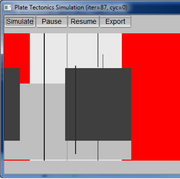 |
| Seeing red |
Friday, February 3, 2017
Plate Tectonics - 9
As I mentioned in my last post on this topic, I believe the erosion algorithm for the Plate Tectonics simulator needs to be tweaked. I've been analyzing the current erosion code and discovered that unlike the original version of PlaTec I worked with that basically used a smoothing algorithm, the version I'm working with now looks to be using the water drop erosion algorithm, akin to what is described as hydraulic erosion in Musgrave's work. In addition to the erosion proper, the function that implements the erosion also introduces some random noise (variations in elevation) every time the erosion function is called. The difference is "splotchy" without random variation vs. "grainy" with random variation, as seen in the image below. Have I discovered the need for yet another parameter?

The current set of parameters is already pretty large. I'm still working all of these parameters into the code base. A lot of them are currently constants. Now they need to go into/come out of the parameters window and get passed to the simulation code.
 |
| Parameter chaos. Perhaps grouping them into labelled groups and changing some into sliders will improve things? In many case, many times just leaving the values as-is works great. But not always. It depends on your goal. |
And I still need to back and fix the problem that I posted about previously, the "caterpillars" and over-eroded mountains. That's why I started looking at the erosion code in the first place. I basically want the land bordering on ocean to erode faster than the mountains. The "caterpillar" islands form from too little erosion of islands in the oceans formed by plate movement. Attempting to prevent the "caterpillars" by increasing the frequency with which erosion is applied causes the mountains to erode too quickly instead.
Conceptually, I think it is as simple as a scalar factor for the amount of material to move when the erosion algorithm moves material from a "high" cell to neighboring "low" cell(s). My first approach would be that the scalar could equal the sum the number of neighbor cells that are below sea level, divide by four (von Neumann neighborhoold, not Moore), plus 0.5. Hence a "high" cell that was inland would erode at half the nominal rate, a single-cell island would erode at 1.5 times the nominal rate, and cells belonging to larger islands or on the coast would erode at an intermediate rate. This actually makes some sense within the context of the simulation, as well, as wave action and rainfall would result in more erosion than rainfall alone. We'll see what it takes to implement that once I fully understand the existing implementation of the erosion algorithm, then how well it works in practice.
Wednesday, February 1, 2017
Plate Tectonics - 8
So close, yet so far. That's the best description of the current state of the Plate Tectonics code. I've got a decent feel for the parameters now, and will be exposing them through the UI so different effects can be achieved. However, there's two different artifacts caused by the erosion period parameter. Run erosion too frequently, and the mountains erode down from something like the Rockies, Alps, and Himalayas, to something more like the lesser portions of the Appalachians or Catskills. Run it too infrequently, and you get long "fuzzy" islands or island chains that remind me of caterpillars. Hours of running simulations show it is almost impossible to find a "happy medium" by simply adjusting the erosion period. I think the erosion algorithm needs to be tweaked to increase the level of erosion for sea-exposed cells and/or decrease it for land-bound cells. Perhaps a scaling factor calculated from the percentage of neighbor cells that are below sea level?
 |
| An example terrain mapped onto a globe |
 |
| Examples of "caterpillar" islands arising from too little erosion |
 |
| Examples of heavily eroded mountains, from too much erosion |
Monday, January 30, 2017
Reading, Writing, and Plate Tectonics
I made more progress yesterday with the Plate Tectonics simulator, almost finishing it. I tweaked the variables and all worked well at a 256x256, 512x256 and 512x512 resolution. Alas, I discovered that when the resolution is increased to 1024x512, certain parameters that are currently constants need to be changed, otherwise the results look clunky. So I need to go back and turn six constants into variables, expose them, and update the UI so they can be altered by the user. Probably another few days for release, because I'll want to run a lot of simulation cycles to be able to set decent defaults and provide recommendations for different setting levels.
My writing of The Forbidden Valley bogged down temporarily, but as I sit drinking hot cocoa, I think I know how to resolve the problem in the scene I'm working on. I'd written ahead of that point, but hadn't been able to resolve the problem in that scene. I think I have now, though, so snippets may be forthcoming again soon.
I read three novels yesterday: Loose Ends by John van Stry, and Scout's Law and The Fugitive Heir by Henry Vogel. All three were a lot of fun and I intend to write reviews when I have a chance - including brief ones on Amazon. I am also continuing with reading Lincoln Paine's The Sea & Civilization, a non-fiction maritime history, and have made it to just short of the one-third mark. This is a long but engrossing work, but is definitely a slower read than the romps provided by the novels I mentioned at the start of the this paragraph.
Sunday, January 29, 2017
That's no Death Star, that's a moon!
The recent image of Tethys from NASA's Cassini mission reminds some of the Death Star, or an eye ball. I think its just plain cool.
 |
| NASA/JPL-Caltech/Space Science Institute - image PIA20518 |
Plate Tectonics - 7
Rectangular maps! At last, I have them. Alas, I must also do a lot of parameter tweaking. One of the peculiarities I'm running into is large numbers of enclosed basins. Initial land masses are formed using fractional Brownian motion (fBm) algorithm that uses OpenSimplex noise as its basis function. Aside from resulting in some enclosed basins (low points) in the land masses to start with, it also results in a number of islands and peninsulas that can result in basins when portions of land masses collide and there isn't enough subduction for the basin to be closed.
This is not totally unrealistic. There are a number of inland seas and massive lakes on Earth. The Caspian and Aral Seas are good examples of the former, and the Great Lakes of the latter. However, they do seem more prevalent in these maps. Perhaps reducing the number of "octaves" for the fBm will reduce that. I'm not sure yet. It will require some experimentation.
So, to summarize, more progress, but not quite done.
Saturday, January 28, 2017
Plate Tectonics - 6
The replacement of the square-diamond algorithm for initial land mass generation has been completed. The OpenSimplex algorithm is now in use instead. It may need some parameter tweaking to achieve quite the right effect, but is providing mostly-satisfactory effects already. Two examples are shown below. So what's left before release? Code-wise, the last alteration is supporting arbitrary map dimensions. The current code base assumes a square map, and there are well over a hundred references to variable map_side. I'm going to have to go through all of them and figure out if each reference needs to be replaced by map_width or map_height. Joy. Hopefully that will be the last of the changes, and then I can look at putting this up on GitHub and figuring out how to distribute the executable.
 |
| Example output from Plate Tectonics simulation |
 |
| Another example output from Plate Tectonics simulation |
Wednesday, January 18, 2017
Orographic effects
Over at Cat Rotator's Quaterly, Alma T.C. Boykin has a post that mentions fog resulting from orographic lifting. This got me thinking. (Dangerous, I know.) Orographic effects abound. Ground fog in the Texas Panhandle is the least of it. Orographic clouds form when moisture in the air rises and cools. This is why clouds are so often observed near the peaks of island mountains in warm waters; the air is most from the surrounding waters, and as that air is pushed up and over the mountains, the clouds form.
When rain then falls from orographic clouds it is known as orographic rainfall. Such rainfall can cause more than just a spot of bad weather, but can impact climate and topography as well. The rain shadow effect of tall mountains, and the often lush environment on the opposite side of the mountain, are a prime example. More rainfall will also typically cause more erosion, which is reflected in more erosional land forms (gullies, ravines, streambeds, etc.) on the wet side than the dry side of the mountains.
Just something to keep in mind when designing a world, be it for a game or a story. And something to account for when writing programs to create worlds, too.
Tuesday, January 17, 2017
A simple digital globe - 4
The simple digital globe from my September posts has had a small update to correct a texture (UV) mapping problem at the north pole. This problem was actually longstanding, but when I was viewing the output from the Plate Tectonics simulator yesterday using it I finally decided to spend the time tracking the problem down and fixing it.
It turns out the distortion results from the vertex sharing required for auto-generating normals that make the polyhedron look like a globe. The fix turned out to be to deliberately introduce minute differences into the y coordinate of the vertex at the north pole, so each triangle at the top had a minutely different vertex position at the top but with much different texture coordinates. The details can be seen in comments in the source code.
The source code is available under MIT license at https://github.com/AnAvidDeveloper/Globe. I will look into making a binary available in the future.
 |
| Globe program displaying output from Plate Tectonics simulator |
It turns out the distortion results from the vertex sharing required for auto-generating normals that make the polyhedron look like a globe. The fix turned out to be to deliberately introduce minute differences into the y coordinate of the vertex at the north pole, so each triangle at the top had a minutely different vertex position at the top but with much different texture coordinates. The details can be seen in comments in the source code.
The source code is available under MIT license at https://github.com/AnAvidDeveloper/Globe. I will look into making a binary available in the future.
 |
| Globe program displaying output from Plate Tectonics simulator, looking at the North Pole. Note the minor distortion at the center (pole), expected of a flat map wrapped around a sphere. That pinching is much improved over the strange swirl that was there before. If there are ice caps, nobody will even notice. |
Sunday, January 15, 2017
Plate Tectonics - 4
I didn't accomplish as much as I'd hoped today, courtesy of Real Life. In any case, I made a bit more progress on the Plate Tectonics simulator. Alas, I also decided to finish up a few things I'd originally though to leave for the future, so I'm not sure I'm actually any closer to completion. [sigh]
In a post yesterday, I mentioned I'd found code for a more recent version of the PlaTec simulator. I've incorporated most of that updated code and done some minor refactoring to better modularize the program. Previously, the simulation and the UI had been a bit too intertwined, legacy of my not having done anything much in C++ for ages, and only second time using the GUI framework in question (FLKT).
So what did that get me? The updated PlaTec code brought better erosion algorithm, fewer visual anomalies, and slightly slower simulation. The refactoring will eventually allow console-based execution as well as the current interactive GUI mode. And I've made a few more parameters accessible via the GUI. However, two parameters that are the GUI no longer accomplish anything. I have to modify the updated PlaTec code to permit the parameters in question to be supplied via code, rather than treating them as hard-coded constants. One of the other features I'd originally considered for a future enhancement, a parameters file, I have decided to at least completed the code for writing to file. Reading in is likely still a future enhancement, but I'd like to know what parameters I used to create any given map.
In a post yesterday, I mentioned I'd found code for a more recent version of the PlaTec simulator. I've incorporated most of that updated code and done some minor refactoring to better modularize the program. Previously, the simulation and the UI had been a bit too intertwined, legacy of my not having done anything much in C++ for ages, and only second time using the GUI framework in question (FLKT).
 |
| Updated parameters dialog box |
So what did that get me? The updated PlaTec code brought better erosion algorithm, fewer visual anomalies, and slightly slower simulation. The refactoring will eventually allow console-based execution as well as the current interactive GUI mode. And I've made a few more parameters accessible via the GUI. However, two parameters that are the GUI no longer accomplish anything. I have to modify the updated PlaTec code to permit the parameters in question to be supplied via code, rather than treating them as hard-coded constants. One of the other features I'd originally considered for a future enhancement, a parameters file, I have decided to at least completed the code for writing to file. Reading in is likely still a future enhancement, but I'd like to know what parameters I used to create any given map.
 |
| Map generated using updated (2015) PlaTec code. Note the greater variation in elevation, as depicted by color variation, as compared to earlier examples. Note also that there are fewer high plateaus. The number of strange islands is also reduced, replaced by more coherent islands. |
 |
| Map created with earlier PlaTec code. Note lesser variation in elevation/color, and greater number of high plateaus. |
Saturday, January 14, 2017
Plate Tectonics - 3
In preparation for releasing the plate tectonics simulator, I went to the site hosting the repository for the original PlaTec simulator, in order to confirm the license was LGPL as I'd thought. I was correct, it was under the GNU Library General Public License. However, I also discovered there was an update to the code two years ago, including some sort of Java-based GUI, and a C API to the code. I'm going to look at incorporating the updated simulation code into my release.
I overslept, then spent a bit of time today helping a friend. As a result, not much progress was made on this project today. However, here's another pair of planets generated with slightly different parameters than yesterday. Increasing the "restart speed limit" parameter from the default 5.2 value generally allows less time for the simulation to run per cycle. Both were generated with nearly identical parameters to each other, but notice the difference one cycle vs. two cycles makes. There are more mountains, and more larger mountains, with two cycles.
I overslept, then spent a bit of time today helping a friend. As a result, not much progress was made on this project today. However, here's another pair of planets generated with slightly different parameters than yesterday. Increasing the "restart speed limit" parameter from the default 5.2 value generally allows less time for the simulation to run per cycle. Both were generated with nearly identical parameters to each other, but notice the difference one cycle vs. two cycles makes. There are more mountains, and more larger mountains, with two cycles.
 |
| Result from seed 53, 1 cycle, 15 plates, sea level 0.75, restart speed 9 |
 |
| Result from seed 53, 2 cycles, 15 plates, sea level 0.75, restart speed 9 |
Friday, January 13, 2017
Plate Tectonics - 2
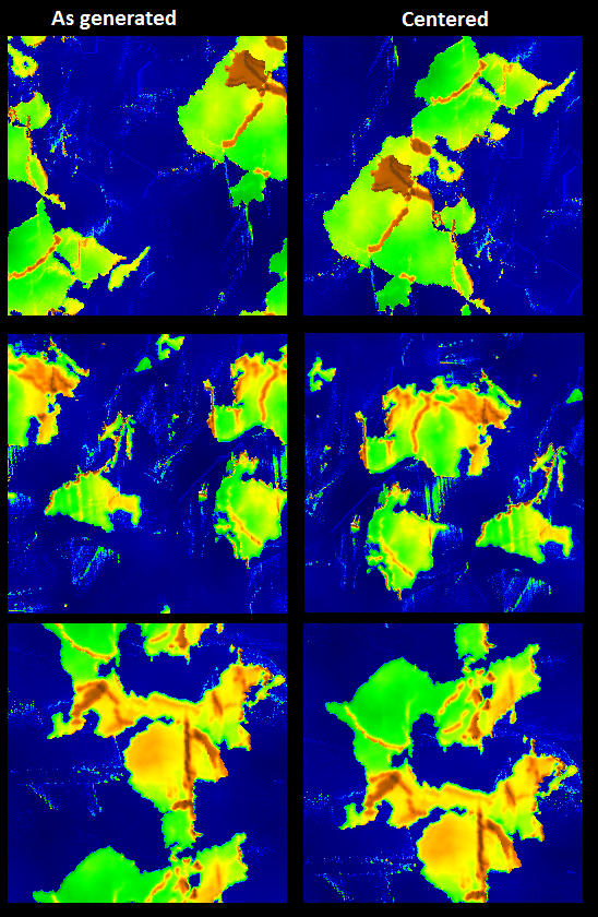
In yesterday's post, I mentioned my efforts to convert Lauri Viitanen's 2012 thesis project, an open-sourced plate tectonics simulator, into something with a GUI that would run on a Windows platform. One of the items I thought still was required was a "centering" feature, to minimize the amount of land wrapping at the edges of the map. I managed to do so tonight, though I will need to make some changes to integrate it better. Still, you can see the results in the examples below. In my (not so) humble opinion, the centered maps on right look far better than the ones on the left, but the only difference is positioning.
Anyhow, aside from integrating the centering code, I would also like to complete the JPEG export. And then I think I shall call this project complete and put it up on GitHub. There's a lot more that could be done with this. In terms of features, it could use some better erosion algorithms. As it stands now, "erosion" is simply a smoothing algorithm applied every so many iterations, and at the end of each cycle. An erosion algorithm that operated on the islands and seacoasts periodically would help reduce some of the odd island growth that is sometimes seen. Additional output formats (image and elevation) might be nice, but probably aren't essential. A header file to accompany the current elevation export would be nice, specifying at minimum the map dimensions and sea level, but possibly the full set of parameters used to generate the map. Really nice would be a different initial landmass generation algorithm, so as to allow non-square, non-power-of-two map sizes.
In terms of the code itself, it could also use some work. When I originally worked on port this program three years ago, it was only the second time I'd used FLTK, and the first time I'd used C++ in years. I'd organize the code a bit differently, especially in terms of classes and how I integrated the output from FLTK's GUI designer, FLUID. Maybe add support for running from command line, too. It wouldn't hurt if I were to write some documentation for this, at least a readme file. That's all for the future, if ever.
And as I wrote that previous sentence, another idea popped into my head. These algorithms take a long time to run the simulation. Perhaps if a large number of maps were generated, the resulting islands and continents (land masses) could be extracted and stored. Then when a new map is required, it could be assembled by random placement of several random selections from the stored land masses. Just thinking aloud here.
Plate Tectonics
I've mentioned before PlaTec, a simple plate tectonics simulation program. This evening a spent a little bit of time working on my old port of it to a Windows environment with an FLTK GUI. I've fixed a few problems, and have added some basic export capabilities. It's pretty basic, really.
First you enter some parameters. Because the initial landmass is generated using the diamond square algorithm, the map must be square, and the dimensions must be powers of two. The cycles indicates the number of cycles - splitting of the world into plates and moving them - that should be performed. The plates indicates the number of plates. Sea level is a number between 0 and 1 approximating how much of the world should be sea. The random seed determines the initial landmass shape as well as coordinates for the plate origins. Restart energy ratio and restart speed limit determine how slow plate movement gets before a cycle ends; IIRC lower numbers tend to let the simulation drag on for longer.
Once the OK button is clicked in the parameters window, the simulation begins. The initial land mass is created, the world is split into plates, and movement begins.
Below are some examples of output. Because the simulation works on a 2D basis and wraps vertically and horizontally, I think a centering feature to be applied upon completion would be useful. As you can see in the examples, the land masses in the end result are often wrapping across the edges; centering would make for more attractive maps. They'd also be more realistic if the north polar region and south polar region didn't wrap. :) Centering accomplishes that in many cases.
First you enter some parameters. Because the initial landmass is generated using the diamond square algorithm, the map must be square, and the dimensions must be powers of two. The cycles indicates the number of cycles - splitting of the world into plates and moving them - that should be performed. The plates indicates the number of plates. Sea level is a number between 0 and 1 approximating how much of the world should be sea. The random seed determines the initial landmass shape as well as coordinates for the plate origins. Restart energy ratio and restart speed limit determine how slow plate movement gets before a cycle ends; IIRC lower numbers tend to let the simulation drag on for longer.
 |
| Parameters for plate tectonics simulation |
 |
| Simulation GUI |
Below are some examples of output. Because the simulation works on a 2D basis and wraps vertically and horizontally, I think a centering feature to be applied upon completion would be useful. As you can see in the examples, the land masses in the end result are often wrapping across the edges; centering would make for more attractive maps. They'd also be more realistic if the north polar region and south polar region didn't wrap. :) Centering accomplishes that in many cases.
I'm going to put in a bit more work to finish up the export - write now it does PNG and RAW images, and a raw elevation dump in floating point - but I also want JPEG support. Also, I think the program needs a centering feature. At that point I'll probably put it up on GitHub. The original version of this simulation was originally a computer science student's thesis project back in 2012, and there's a paper on it. He released the code under an LGPL license and placed the source code on Source Forge. All I've done really is provide a GUI that will work with Windows.
This simulation can produce some nice crude planet maps, but it is slow. Tens of minutes may go by for completion using the 512x512 and only a single cycle.
 |
| Seed 44 with 1 cycle |
 |
| Seed 44 with 2 cycles |
 |
| Seed 45 with 1 cycle |
Sunday, December 18, 2016
Dealing with the Great Big World 3
I've discussed some of the terrain-related portions of dealing with the Great Big World before. I'm going to touch on another aspect in this post - buildings.
I'm working on the (software) architecture for a fresh prototype for the splines and sketching that I've posted about in the past. I'd originally planned to continue work with that prototype, but the architecture is just poorly suited as it stands now. I'll be reusing a lot of the code, but trying to shoehorn the changes into the original prototype wasn't working well. Nothing from that is even close to ready to show, though. So let's discuss buildings.
I'm working on the (software) architecture for a fresh prototype for the splines and sketching that I've posted about in the past. I'd originally planned to continue work with that prototype, but the architecture is just poorly suited as it stands now. I'll be reusing a lot of the code, but trying to shoehorn the changes into the original prototype wasn't working well. Nothing from that is even close to ready to show, though. So let's discuss buildings.
 |
| The old prototype, showing a river, road, railroad, and three buildings. |
There are three buildings in the screenshot above, represented by the dark blue-gray polygons at upper left, near where the railroad crosses the road (to get to the other side). For a decent 3D representation, what would we do? We could substituted manually-modeled building models, be they free, purchased, or created personally. But imagine trying to store a 3D model for every planet on a building, let alone model them all. Its not very practical, although it is perfectly feasible to do for some signature structures, such as a few buildings in a national capital, or the tallest, signature skyscrapers in a city. What does that leave us as an alternative? Procedural modeling of buildings.
That's start with a very simple form of procedural modeling. Our starting point will be the polygons in the map that represent buildings. Each such polygon is the footprint of a building. If each such a polygon were extruded upwards, we would get a polyhedron from each polygon.
That's start with a very simple form of procedural modeling. Our starting point will be the polygons in the map that represent buildings. Each such polygon is the footprint of a building. If each such a polygon were extruded upwards, we would get a polyhedron from each polygon.
 |
| Extrusion process - from polygon to polyhedron |
But that only gives us a simple three dimensional form. We could apply a texture to it. If there's a nice tiling (repeatable) texture for brick or stone, it could allow one to accept the polyhedron as a building - especially if some windows and doors were part of the pattern. This may even work well enough in some scenarios, in fact. If each polyhedron had a random texture from a set of of such textures assigned, the buildings wouldn't all look alike, either. A couple examples of such textures, generated via Filter Forge 5 filters, are shown below. It might be good enough for a flight simulator or a train simulator, or for more-distant background buildings in any game or simulation.
 |
| Brick texture created using filter Bricks version 1 |
 |
| Window in wall texture created using filter Window gen |
For buildings that are more close up, as in a driving game, a first person shooter, or just a VR scenario that involves walking down the street, it'll fall flat pretty fast. Thankfully, there are solutions. There are plug-ins and packages for many game engines and modeling tools that will help with some of this. Unity features the BuildR asset in its Asset Store, for example. And then there's perhaps the ultimate expression of procedural building generation, ESRI's CityEngine.
ESRI is primarily a GIS (geographic information systems) company, producers of the ArcGIS product. However, they purchased a company out of Zurich named Procedural, Inc. that had produced a product called CityEngine. CityEngine can create entire cities, including detailed building models. For building generation, it uses something called CGA Shape Grammar. CGA Shape Grammar is discussed at length in a 2006 paper by Pascal Mueller, Peter Wonka, Simon Haegler, Andreas Ulmer, Luc Van Gool, Procedural Modeling of Buildings. You can look at that paper and the online documentation for CityEngine if you want to learn all the details, but I'll cover a few high points below, greatly simplified.
Basically, CGA Shape Grammar is a production system like L-systems in which a set of rules are defined. When fed some initial data (such as the polygon of the building footprint) the rules are iteratively applied and a building is generated. The rules can use operators such as extrude and split to manipulate the 3D dimensional polyhedron or the polygon faces. Extrude works in much the manner as described above.
Split lets a polyhedron or polygonal face be split into multiple parts, so different rules can be applied to different parts. For example, in the image below a polyhedron has been split in two and two different textures have been applied to the top half and the bottom half. This is a common scenario. Note the difference in fenestration between the first and second stories in the photo.
Implementing split of a polyhedron or polygon is fairly simple. Since the polyhedron is little more than a collection of polygons, splitting a polyhedron is simply a matter of splitting the polygons. A plane defines where splitting takes place. See Graphic Gems V "Spatial Partitioning of the Polygon by a Plane" for details on implementing such an algorithm.
The split operation in CGA Shape can take a set of mixed absolute and relative dimensions for the split operation. This involves calculating a set of planes to split by. The splits are then performed sequentially. The outputs of the split can then be addressed by further rules.
ESRI is primarily a GIS (geographic information systems) company, producers of the ArcGIS product. However, they purchased a company out of Zurich named Procedural, Inc. that had produced a product called CityEngine. CityEngine can create entire cities, including detailed building models. For building generation, it uses something called CGA Shape Grammar. CGA Shape Grammar is discussed at length in a 2006 paper by Pascal Mueller, Peter Wonka, Simon Haegler, Andreas Ulmer, Luc Van Gool, Procedural Modeling of Buildings. You can look at that paper and the online documentation for CityEngine if you want to learn all the details, but I'll cover a few high points below, greatly simplified.
 |
| Geometric primitives |
Basically, CGA Shape Grammar is a production system like L-systems in which a set of rules are defined. When fed some initial data (such as the polygon of the building footprint) the rules are iteratively applied and a building is generated. The rules can use operators such as extrude and split to manipulate the 3D dimensional polyhedron or the polygon faces. Extrude works in much the manner as described above.
Split lets a polyhedron or polygonal face be split into multiple parts, so different rules can be applied to different parts. For example, in the image below a polyhedron has been split in two and two different textures have been applied to the top half and the bottom half. This is a common scenario. Note the difference in fenestration between the first and second stories in the photo.
 |
| Polyhedron split process |
 |
| Note difference in windows between first and second floors. |
 |
| Polygon split process |
The split operation in CGA Shape can take a set of mixed absolute and relative dimensions for the split operation. This involves calculating a set of planes to split by. The splits are then performed sequentially. The outputs of the split can then be addressed by further rules.
I am not planning to implement the full CGA Shape Grammar system as described in the paper. Even the rule-based approach is probably more than I care to bother with. However, a few of the operations defined therein could be useful. If the CGA Shape Grammar style of extrude, split, and repeat operations are implemented as C# methods that are part of a broader set of geometric primitives and procedural modeling capabilities, C# code or PowerShell scripts could access them. Combined with Constructive Solid Geometry (CSG) techniques they could provide a very compact representation of buildings without requiring prohibitively-extensive modeling. Can a few scripts generate the buildings for an entire world? Perhaps.
(PS - The roof generating operations would be nice to have for residential architecture. More thoughts on that later.)
Subscribe to:
Posts (Atom)